E5061B Network Analyzer 5 Hz to 3 GHz
Ultimate general-purpose network analyzer
Contents
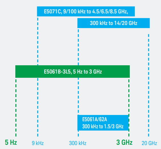
The Keysight Technologies, Inc. E5061B is the latest addition to the industry-standard ENA Series Network Analyzer. The option E5061B-3L51 expands the frequency range down to 5 Hz for network analysis, while covering the most frequently-used RF ranges up to 3 GHz. The established RF network analysis technology of the ENA Series is seamlessly integrated with the full-fledged low-frequency network analysis functionalities in a compact box. The E5061B-3L5 LF-RF network analyzer addresses a variety of network measurement needs with its broad frequency coverage, excellent performance, and versatile functionalities. This technical overview describes features and provides application examples of the E5061B-3L5.
ENA Series Lineup
E5061B-3L5 Key Features
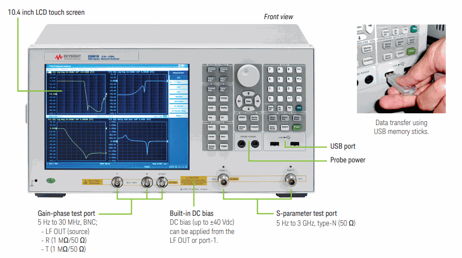
– 5 Hz to 3 GHz frequency.
– S-parameter test port (5 Hz to 3 GHz, 50 Ω).
– Gain-phase test port ( 5 Hz to 30 MHz, 1 MΩ/50 Ω).
– Wide dynamic range.
– Built-in DC bias source (up to ±40 Vdc).
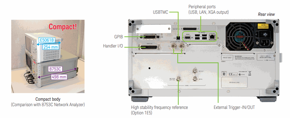
– Compact form factor.
Supports general and advanced network analysis
The E5061B is equipped with high-performance measurement functions and modern user interfaces such as Windows OS, a touch screen panel, and USB memory. These functions not only enable you to evaluate your devices in more detail but also help you improve measurement efficiency.
“One for every lab”
Respond to a variety of measurement needs in R&D using a single instrument
With its basic and useful S-parameter measurement ability in a wide frequency range, the E5061B can help you in a variety of measurement areas. Meanwhile, the uncompromised performance in a low frequency (LF) range along with the gain-phase test port strongly supports you in designing LF components and circuits.
For example, for high-reliability electronic equipment such as automotive, medical, analytical, and aerospace & defense, the E5061B-3L5 enables you to evaluate various kinds of components and circuits used in this type of equipment. The broad coverage for low-frequency devices such as DC-DC converters and sensor circuits to RF devices used in the radio systems and wireless interfaces enables you to improve the performance and quality of your end products.
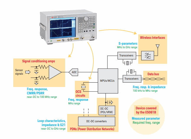 E5061B-3L5 covers wide applications in high-reliability electronic equipment.
General S-parameter measurements from 5 Hz to 3 GHz
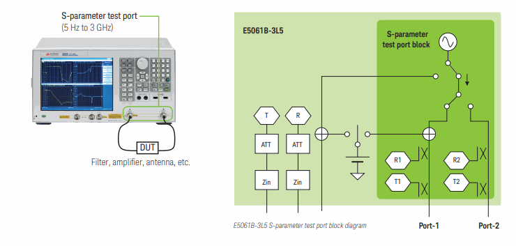
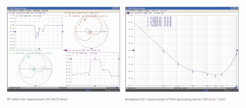
The built-in 50 ohm S-parameter test set of the E5061B-3L5 fully covers the frequency range of 5 Hz to 3 GHz. It enables you to measure S-parameters of not only RF devices such as filters, amplifiers, and antennas but also low-frequency devices such as xDSL filters and power-line EMI filters at the same test ports without using external test sets. It also allows you to evaluate broadband devices such as data cables, transformers, PDNs (power delivery networks), and broadband amplifiers over a wide frequency range with a single sweep.
Excellent dynamic range performance
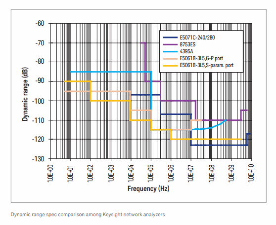
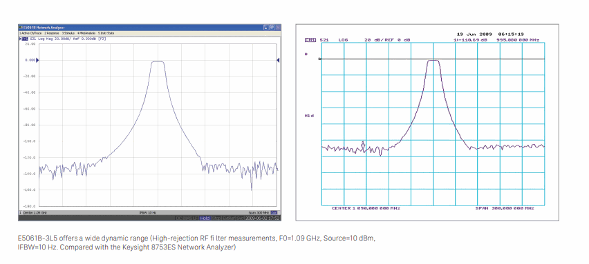
The E5061B-3L5 offers a wide dynamic range performance that is comparable or superior to other high-end LF and RF network analyzers. A key advantage over other network analyzers is the excellent dynamic range in the lower frequencies up to 10 MHz. This is beneficial not only for low-frequency applications but for applications around 100 kHz to 10 MHz.
High-impedance probing measurements using gain-phase test port
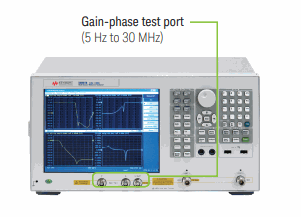
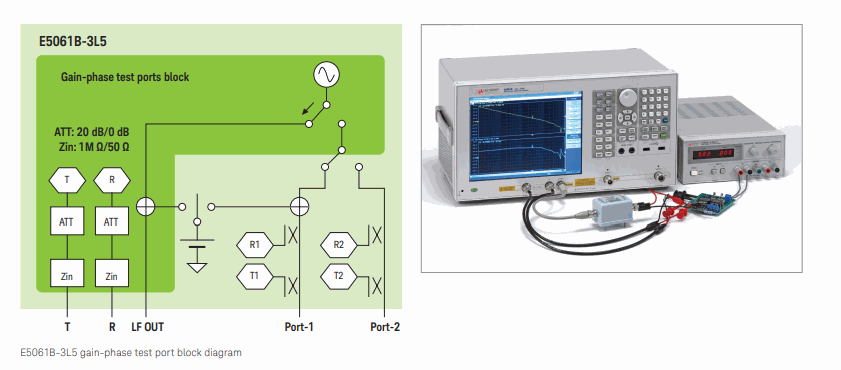
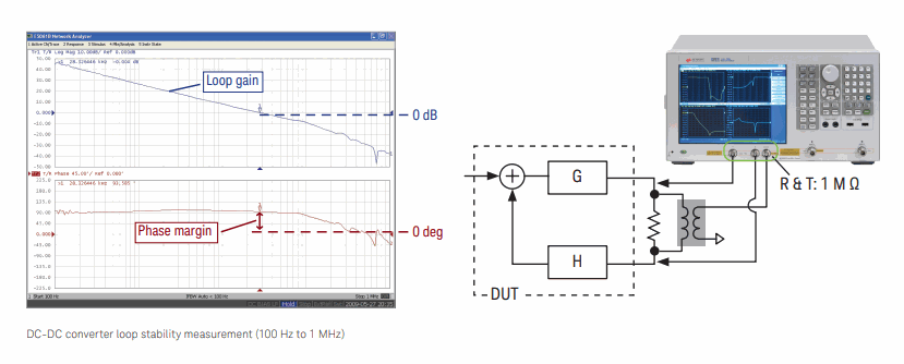
In addition to the S-parameter test port, the E5061B-3L5 is equipped with the gain-phase test port for low-frequency applications that require direct source and receiver access and high-impedance probing. The gain-phase test port enables you to easily perform high-impedance probing measurements for low-frequency amplifiers, and control loop circuits such as DC-DC converters. The test frequency range of the gain-phase test port is 5 Hz to 30 MHz. The input impedance of R and T receivers is switchable to 1 MΩ//30 pF and 50 Ω. Each receiver has an internal attenuator (0 dB/20 dB, manually selectable) and you can optimize the receiver’s full-scale input level and the receiver noise floor depending on the DUT’s output level and the attenuation of passive probes connected to the receiver.
High-impedance probing measurements using an active probe
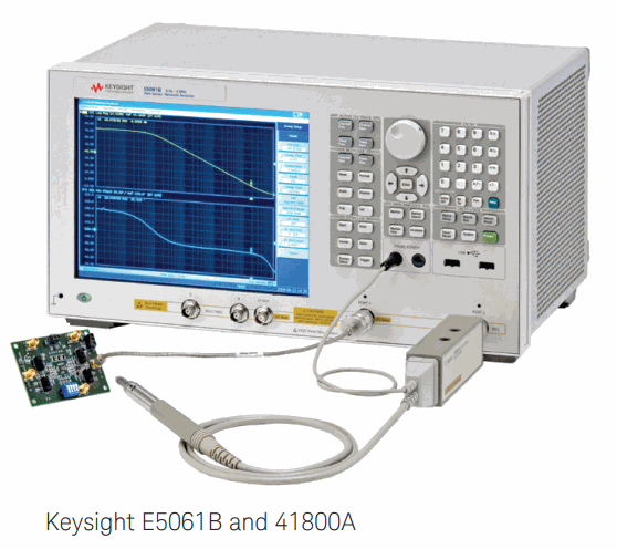
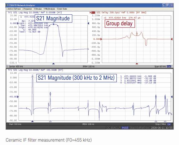
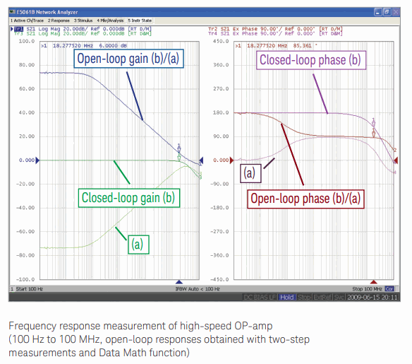
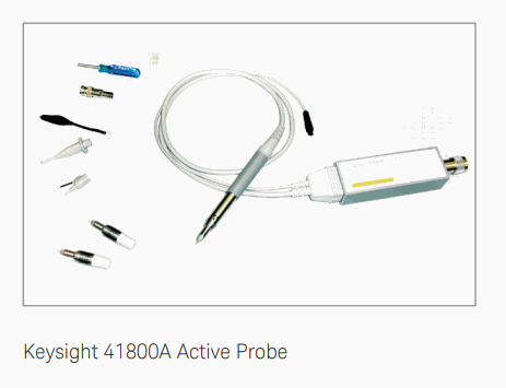
The E5061B-3L5 also has built-in probe powers for connecting an external active probe. This enables you to perform high-impedance probing measurements for devices that must be tested at higher frequencies than 30 MHz, such as highspeed OP-amps, and for devices that require very small probing capacitance, such as ceramic IF filters, oscillator circuits, and antenna coils. The Keysight 41800A active probe is the best choice for these applications.
High-attenuation measurement with ease
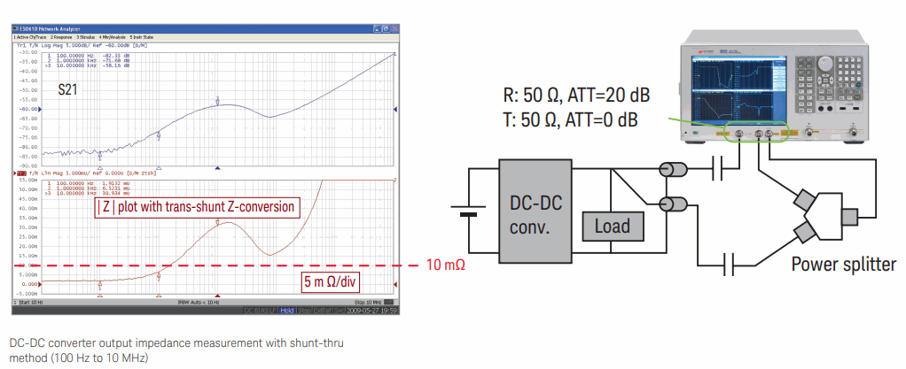
In high-attenuation measurements where there are shunt signal paths at the DUT, the actual measurement dynamic range of general network analyzers is degraded in the low-frequency range due to the measurement error caused by the test cable ground loop between the source and receiver. This is a common problem that occurs in conventional network analyzers, and even in the S-parameter test port of the E5061B-3L5. To reduce this measurement error, it is necessary to attach magnetic cores or an isolation transformer to the test cables. This is troublesome and not easy to fully eliminate the measurement error, especially at a very-low-frequency range.
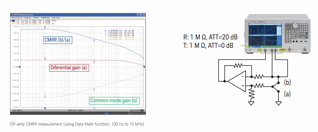
The gain-phase test port of the E5061B-3L5 solves this problem. The gain-phase test port has an internal hardware architecture that minimizes the test cable ground loop, and provides wide dynamic range down to 5 Hz without using external magnetic cores or isolation transformers. The gain-phase test port enables you to easily measure high attenuation parameters of low-frequency devices, such as CMRR/PSRR of OP-amps, milliohm impedance of DC-DC converters, and bulk decoupling capacitors mounted on power delivery networks. Evaluating these critical parameters improves the reliability of analog signal chains and the power integrity of high-speed digital circuits in electronic equipment.
DC-biased measurements
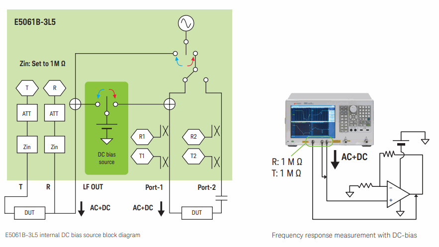
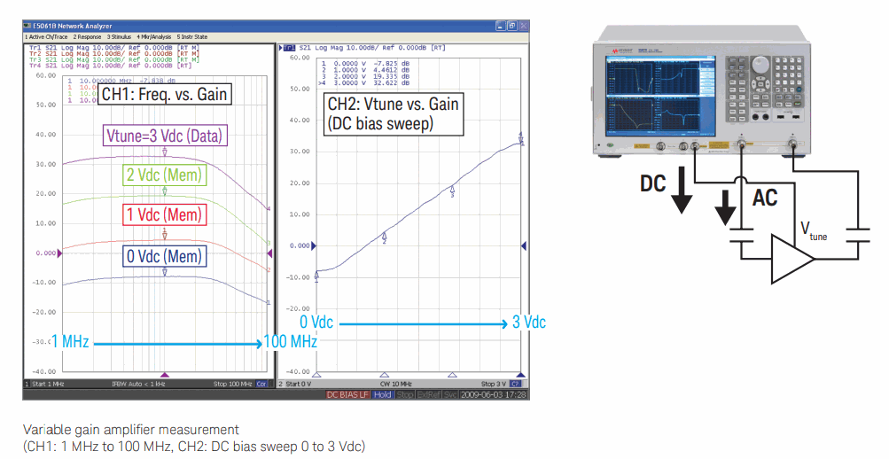
The E5061B-3L5 is equipped with a built-in DC bias source as a standard feature, which supplies a sweepable DC bias voltage from 0 to ±40 Vdc. This unique feature improves efficiency for evaluating amplifiers and other devices that require DC-biased measurements.
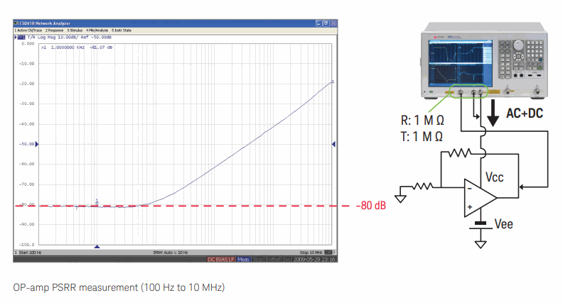
The DC bias can be internally superimposed to the source signal in the measurements at the gain-phase test port or the S-parameter test port. This function allows you to easily perform DC-biased transmission and reflection measurements from a low-frequency range down to 5 Hz. It is very useful for evaluating frequency responses of single-supply amplifiers, DC-bias vs. gain characteristics of video OP-amps, PSRR of amplifiers, and so on...
Using as a sweepable DC source
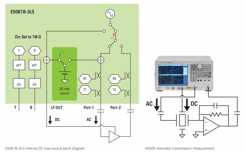
For measurements at the S-parameter test port, the built-in DC bias source can supply only DC voltage via the LF OUT port, while supplying the AC test signal at port-1 and -2. The output impedance of the LF OUT port is 50 ohm. This function is very useful for evaluating voltage-tunable devices that have separate DC bias terminals, such as MEMS resonators, variable gain amplifiers for ultrasound system, other medical/analytical systems, tunable antennas, and so forth.
Useful functions
The E5061B-3L5 is equipped with many other functions that are not available in existing low-frequency network analyzers. These functions will help you to easily achieve your measurement application goals.
DC monitor
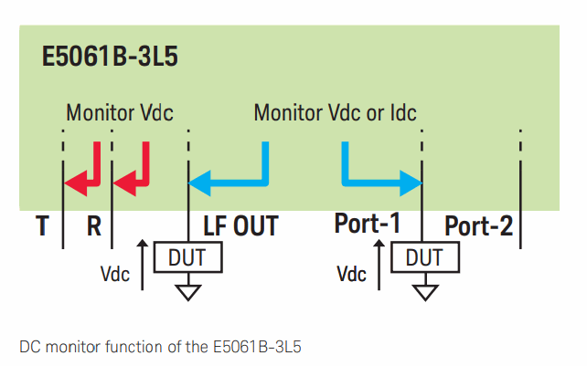
The E5061B-3L5 is equipped with a DC monitor function that can be used for either one of the following purposes;
– Monitoring the actual DC bias voltage (or current) that is applied to the DUT from the LF OUT or port-1
– Monitoring the DC voltage of the DUT at either port R or T
Point trigger capability
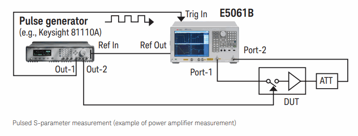
The point trigger (trigger-on-point) function and the trigger IN/OUT ports allow you to expand the E5061B’s measurement capabilities. Application examples are;
– Pulsed measurement by applying external trigger pulse point-by-point for evaluating power amplifiers.
– Point-by-point synchronization with external measurement instruments (such as DMMs and USB power sensors) by programming the test sequence with the built-in VBA or an external PC.
Time-domain/Fault location analysis
The option E5061B-010 time-domain/fault location analysis allows you to locate the discontinuities and mismatches of devices such as cables. By employing the gating function in the time domain and transforming the data back to the frequency domain, you can remove unwanted responses of connector mismatch in your fixture. In addition, the cable SRL (Structural Return Loss) analysis capability is provided with option E5061B-010.
Efficient data analysis
The E5061B also has convenient software tools that help you improve measurement efficiency. You can minimize the time required for data analysis by utilizing these tools.
Equation Editor
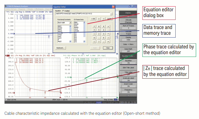
The built-in equation editor function enables you to plot user-defined parameters derived from measured S-parameters, such as differential input impedance/return loss, cable characteristic impedance, transfer impedance, K-factor, and other amplifier parameters. Once the equation is defined, the analyzer automatically calculates and plots the user-defined parameters in real-time.
VBA programming
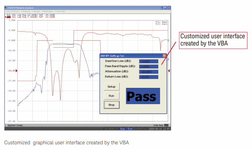
The E5061B is equipped with Visual Basic for Applications (VBA), which allows you to create and run a macro within the analyzer. You can further improve usability by creating a customized graphical user interface and automating your measurement. The program can be developed using the built-in VBA editor.
Key specifications
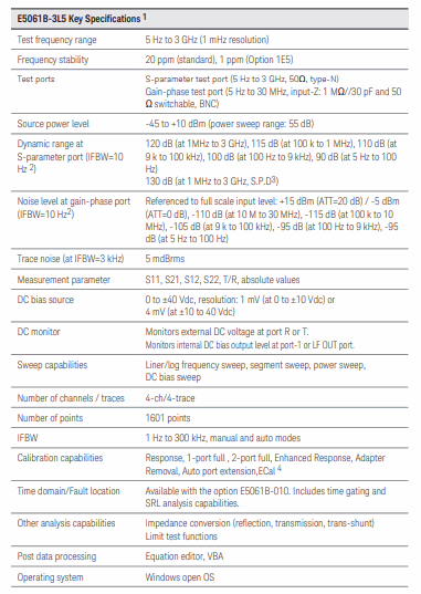
1. For additional specification details see the Keysight E5061B Network Analyzer Data Sheet (literature number 5990-4392EN) available on our web site; http://cp.literature.keysight.com/litweb/pdf/5990-4392EN.pdf
2. IFBW=2 Hz at <100 Hz
3. S.P.D. (Supplemental Performance Data) represents the value of a parameter that is most likely occurs.
4. The applicable frequency range is above 300 kHz for 2-port ECal modules, and above 9 kHz for the 4-port ECal module N4431B.
